Donald - Jordan - Series-Drogue (JSD) – Upgrade of the Sailing Vessel
This article is a translation of a part of "Jordan-Treibanker ... eine Recherche".
Written by me originally in German I translated this essay into English. Please excuse the linguistic errors.
I hope the meaning is comprehensible and the informations may offset my restricted English.
The Jordan-Series - Drogue
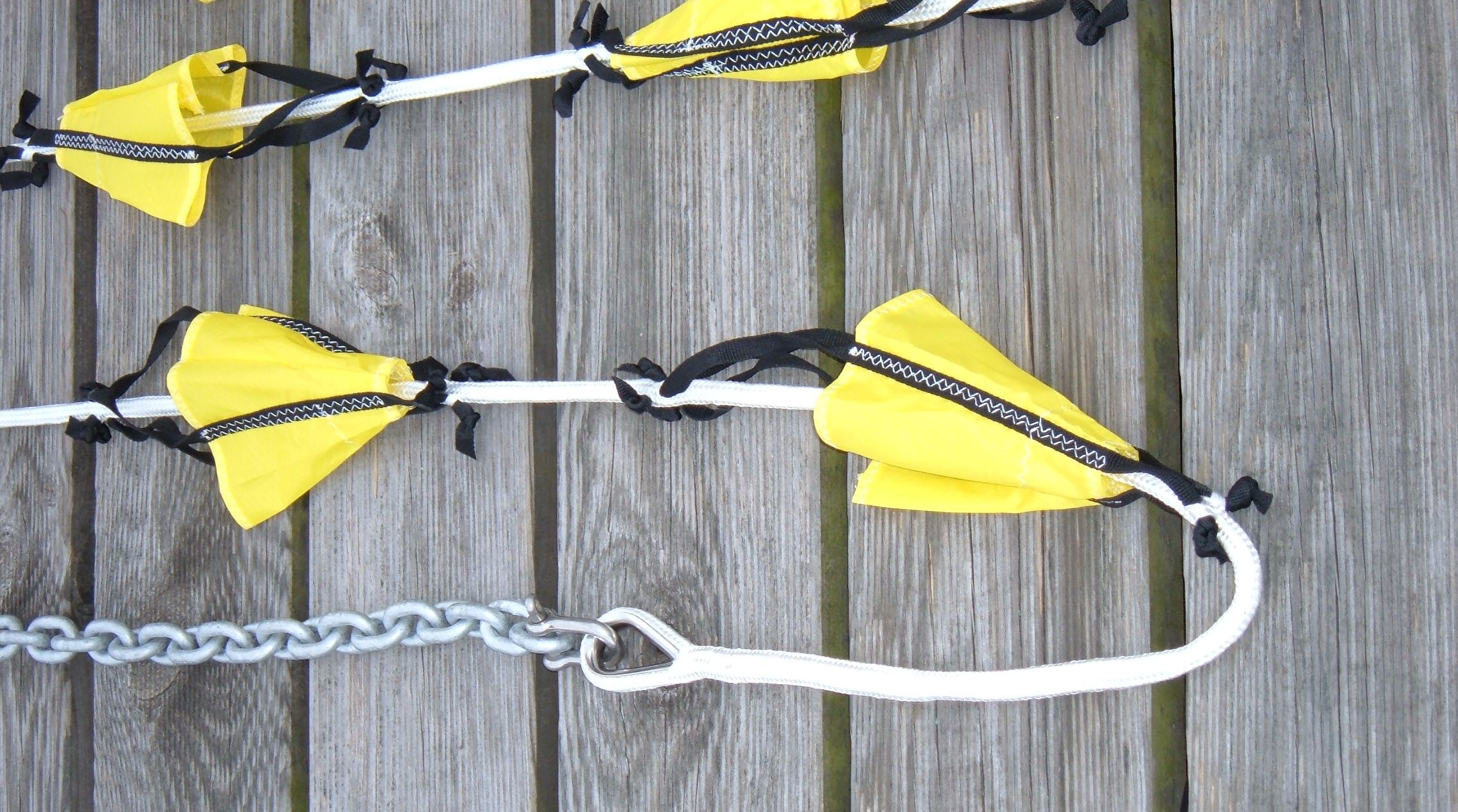
Cones of Dacron, sewn onto the drag line.
The number of the cones comply with the displacement of the yacht.
A weight is rigged at the end of the cable. The purpose is to keep the system below the surface of the water and to keep it under tension.
Between the attachments at the stern and the the dragline there is rigged a "bridle" consisting of two ropes who form a "V".
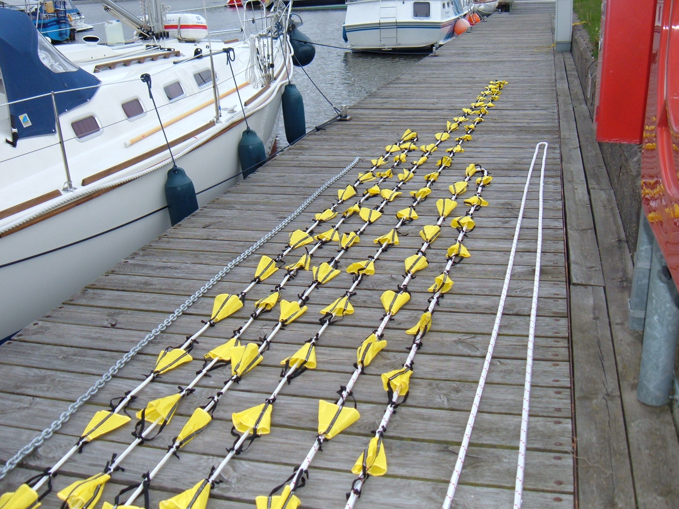
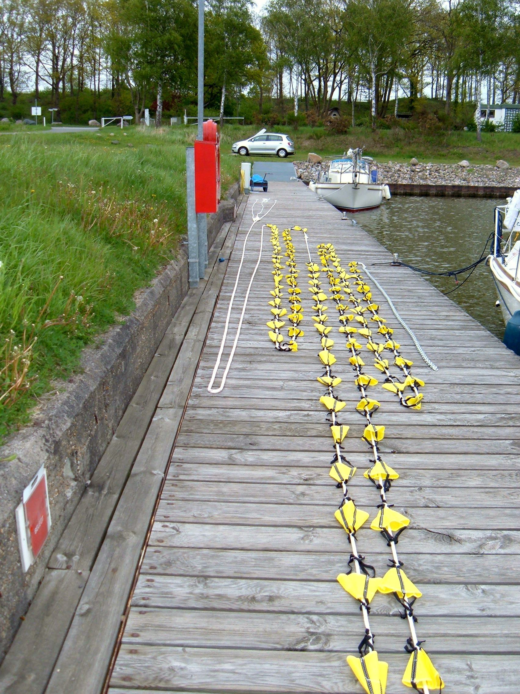
Example of a Jordan - Series - Drogue, displacement of the yacht: 8 t.
- Length of the drag line: 76 m
- Number of cones: 107
- Length of the bridle: (2,5 times the width of the stern), for instance a stern of 2.00 m: 5.00 m
- Weight at the end: 7 kg, for example a chain
The forces, which a boarding breaker may exert to the yacht, are frightening:
• When a yacht is hit by a breaking sea, the acceleration rate amounts up to ~ "2 g" (g = gravity).
If somebody not buckled would be speeded up by 2 g for 1 sec he would catapulted through the cabin after this second with ~ 70 km/h,
• The safety harnesses should withstand up to "4 g".
During the acceleration by the wave the yacht first will be straightened by the JSD, that means she is moved circularly prior to deceleration.
Waist harness or three-point belts like those in cars would be better than to hook the lifebelt somewhere in the cabin.
• The stern of the yacht, the companionway and the walls of the cabin (next to the cockpit)
Presumed the companionway door is 1 m2. Then a weight of 1 ton (1000 kg !) would press against the companionway,
• At a yacht with the displacement of 8 t the conusses of canvass generate a draw of ~ 6000 kp.
A yacht of 9 t would generate ~ 6700 kp. (More about that later.)
Metal Yachts
For owners of metal yachts things are relatively simple.
Presumably one wants to replace the panels of the companionway. Best would be plates from carbon. But they are not cheap.3)
A bidirectional carbon fibre plate of 2 mm thickness (better 3 mm) should be enough so that it should not crack by the expected water pressure.
My friend, Dr. Ing. Ullrich Schleicher, would build a kind of “shield”, which overlapps the companionway lateral,
The shield has to be fastened securely, because it will be accelerated with 2 g may be in any direction.
At the transom there would have to be welded metal rings, to which the JSD is shackled.
Ring thickness and diameter of the shackle bolt at least 15 mm (steel) for a yacht of 8 t displacement (see below).
GRP - and Wooden Yachts
Attachment points for the JSD
Jordan advises explicit against putting the JSD over clamps or winches; they could be pulled out of the deck.
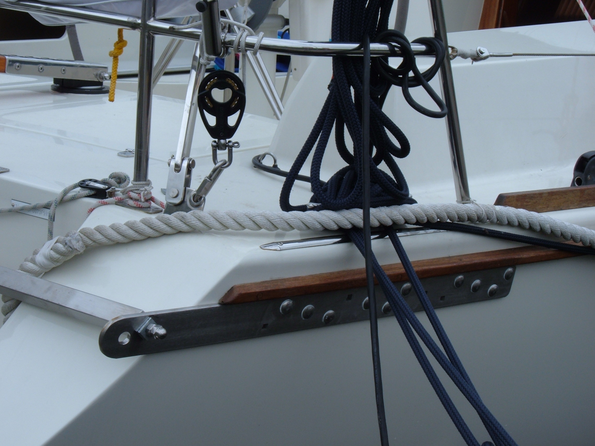
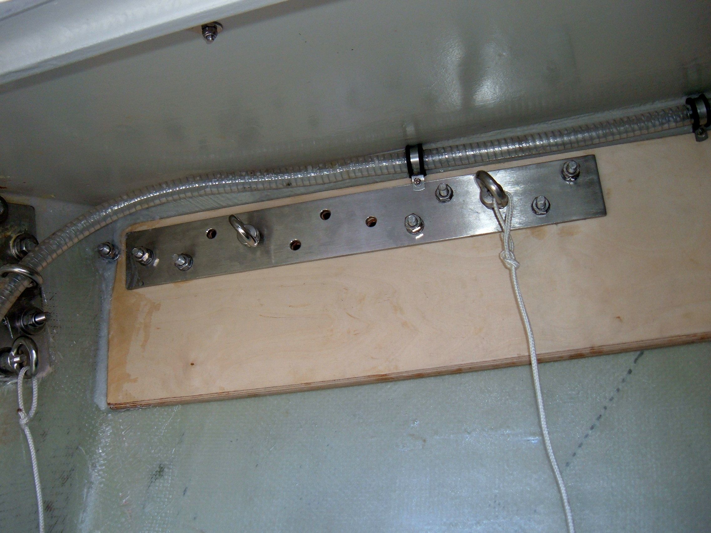
The stainless steel plates are to be provided with drillings at the place, where the JSD is hooked by shackles.
David Lynn lists measures of these stainless steel plates for various sizes of yachts; he uploaded photos, too.5)
This in turn will make necessary a long stainless steel plate of 700 x 70 x 70 x 10 mm.
According to Lynn it has to be attached with bolts of 10 mm in diameter. This I consider overdone.
If a shackle bolt of 20 mm in diameter (stainless steel) is enough (look next section) then 4 bolts of 10 mm each should do as well.
The distance between the aft edge of the hole which should take the shackle of the JSD and the end of the stainless steel plate

David Lynn speaks about reinforcing the hull of a GRP-vessel by additional layers of glass fiber at the attachment points.
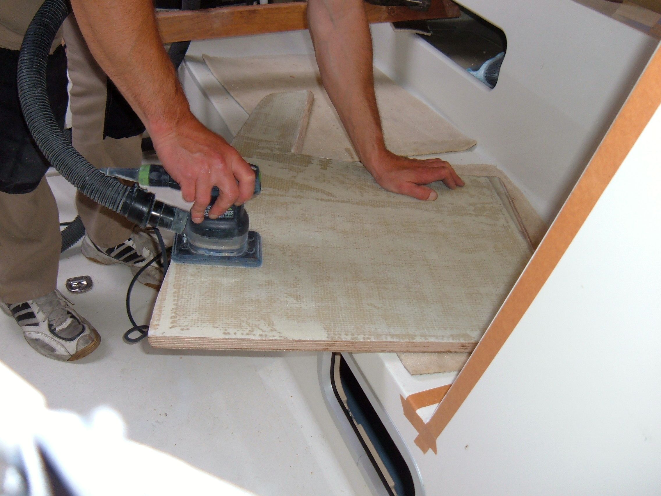
With my own yacht, a woodchore-epoxy-boat (i.e. a yacht whose inner layer of the sandwich construction is made from wood),
Second and particularly important is a massive counter plate in addition (stainless steel, 6 mm) measuring the same like the plate outside.
Therefore I would support the area by marine plywood at the place where outside the stainless steel strip will be attached.
Only now it is possible to attach the 18 mm plywood panel mentioned above plus the stainless steel plate.
It is highly recommendable to consult an expert.
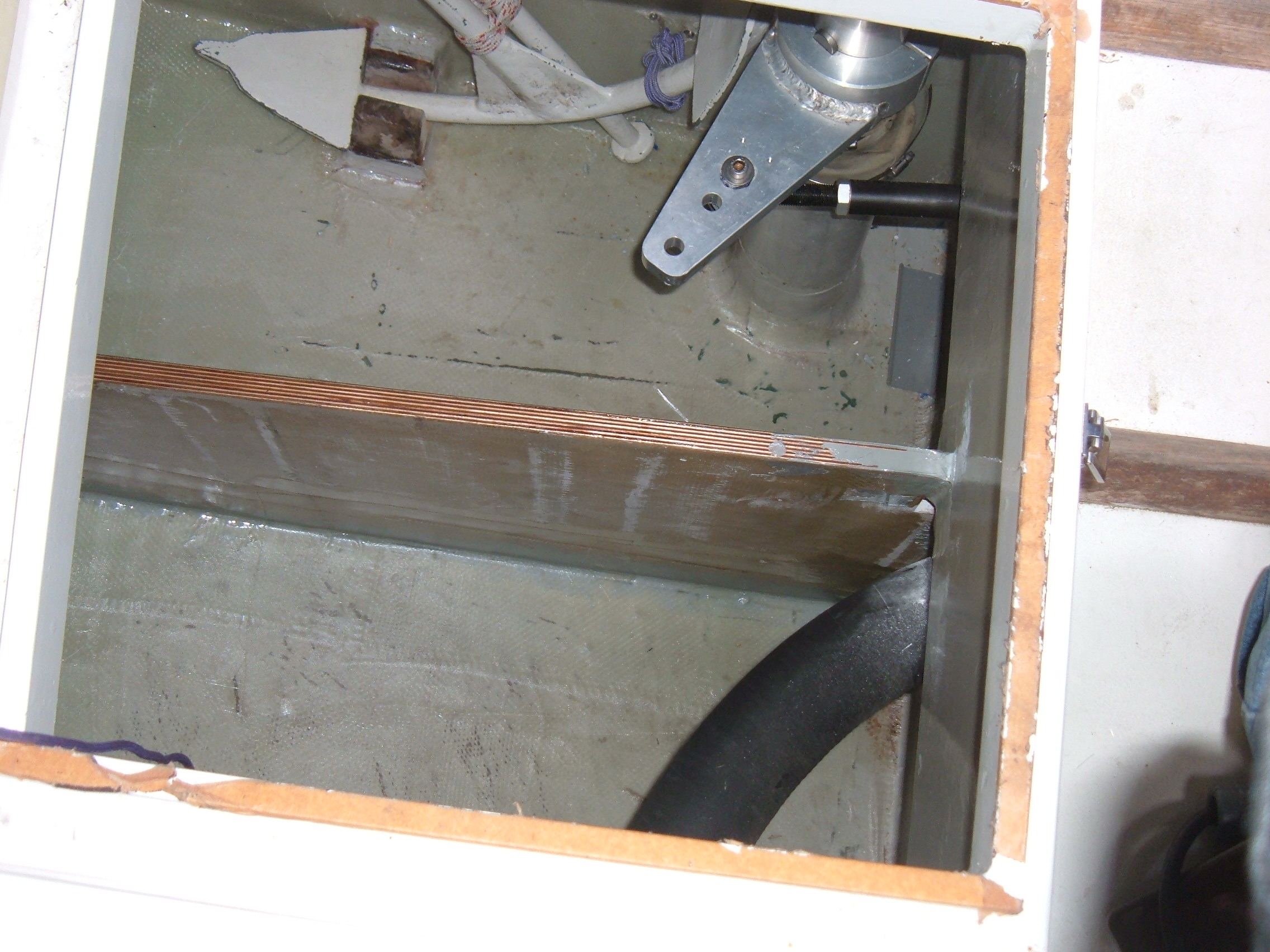
Furthermore in his opinion it has to be checked whether the bracings of the stern would be strong enough.
A square tube as a support, made from stainless steel, fitted exactly between the stainless steel attachment plates
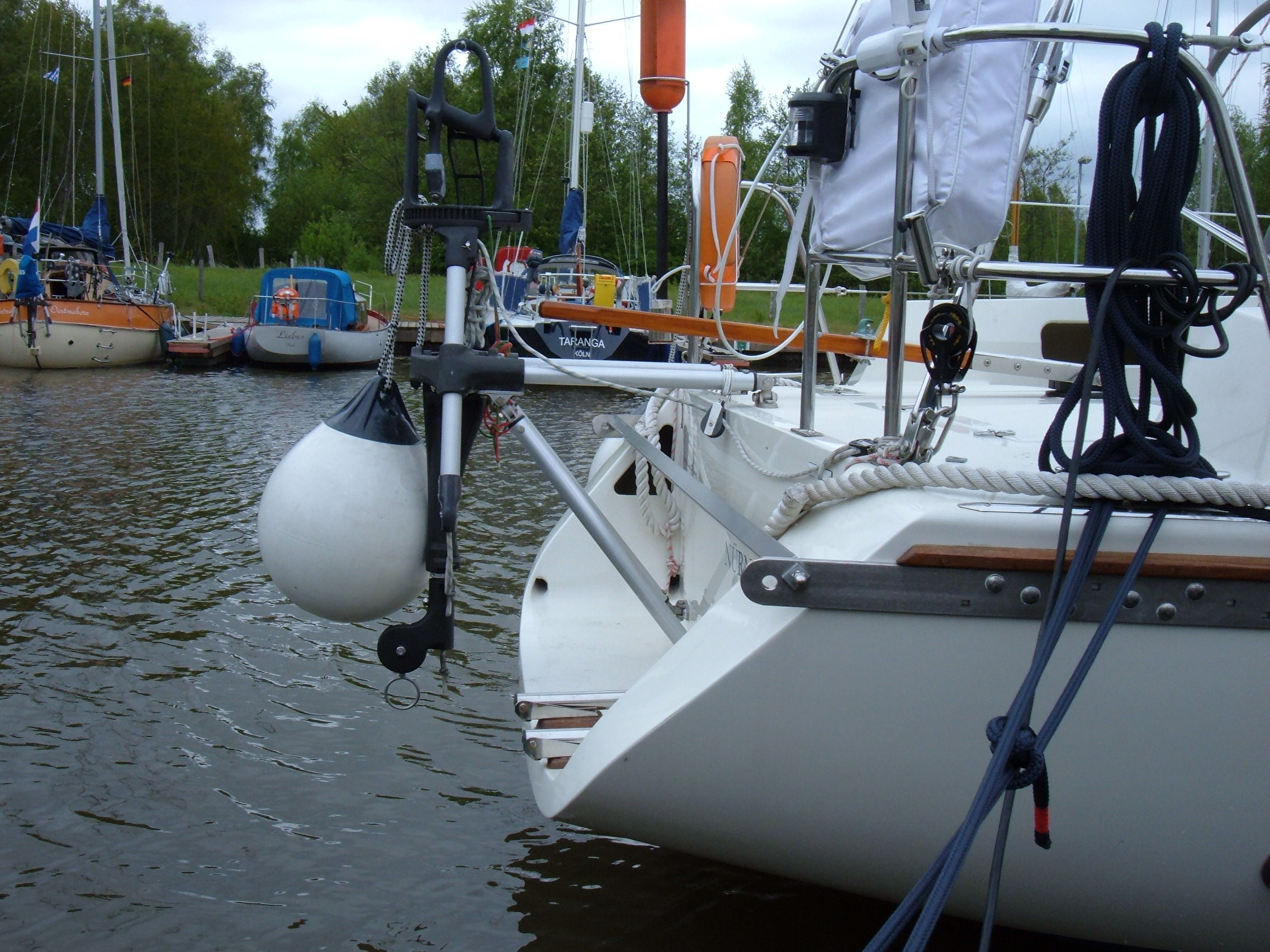
Don`t confuse with the (round) support tubes of the Aries self steering.
It seems to be relatively easy to reinforce the stern with rovings.
Maybe you opt for additional supporting walls lengthwise (… which should be supported for their part).
The same applies to the …
Cockpit – cabin - wall
It should be reinforced at any rate.
On my own yacht I did it by marine ply of 18 mm in combination with 2 layers of glass rovings 500 gr/m2.
But I am not sure whether the supportment of the cockpit-cabin-wall itself withstands.
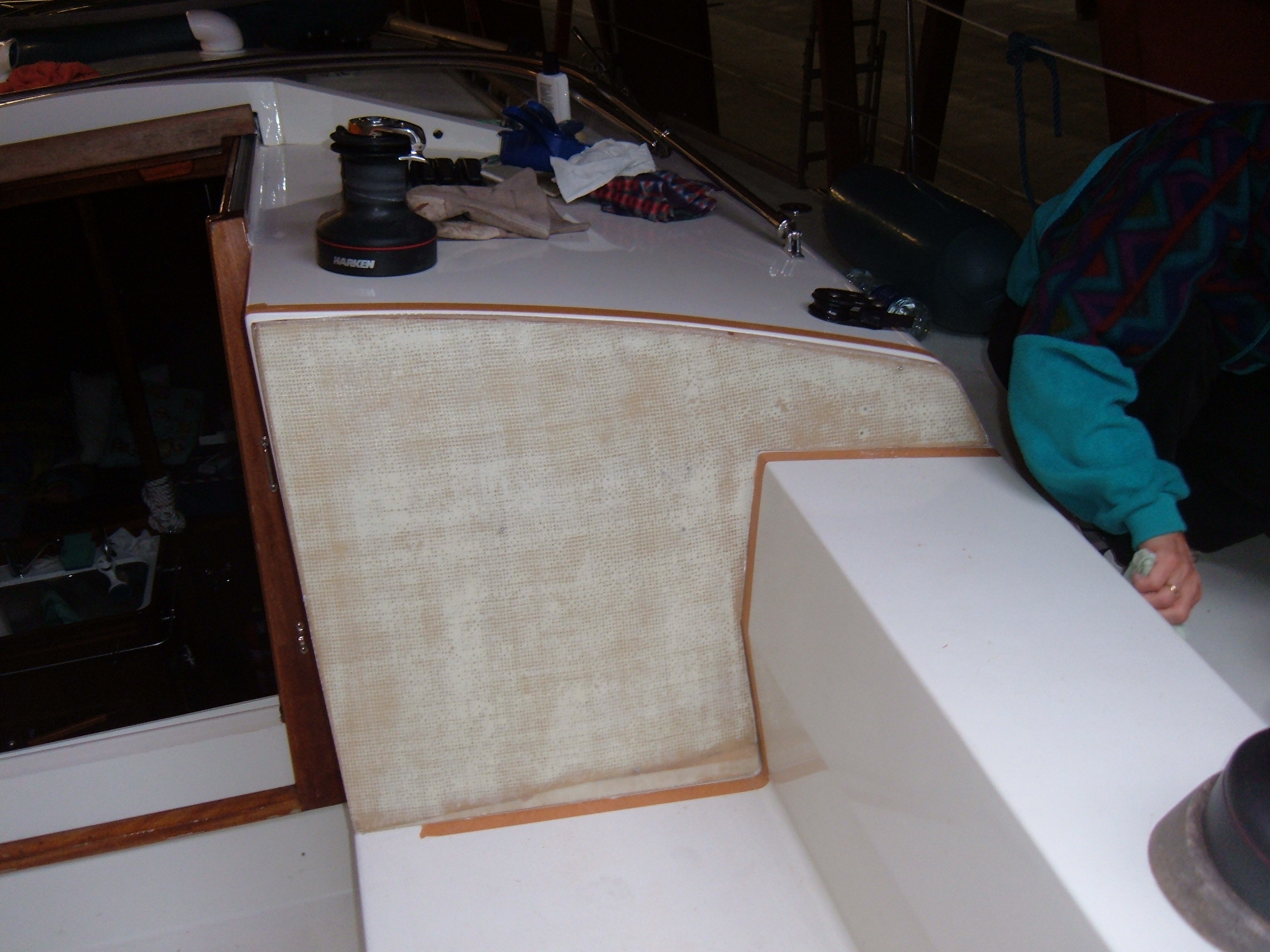
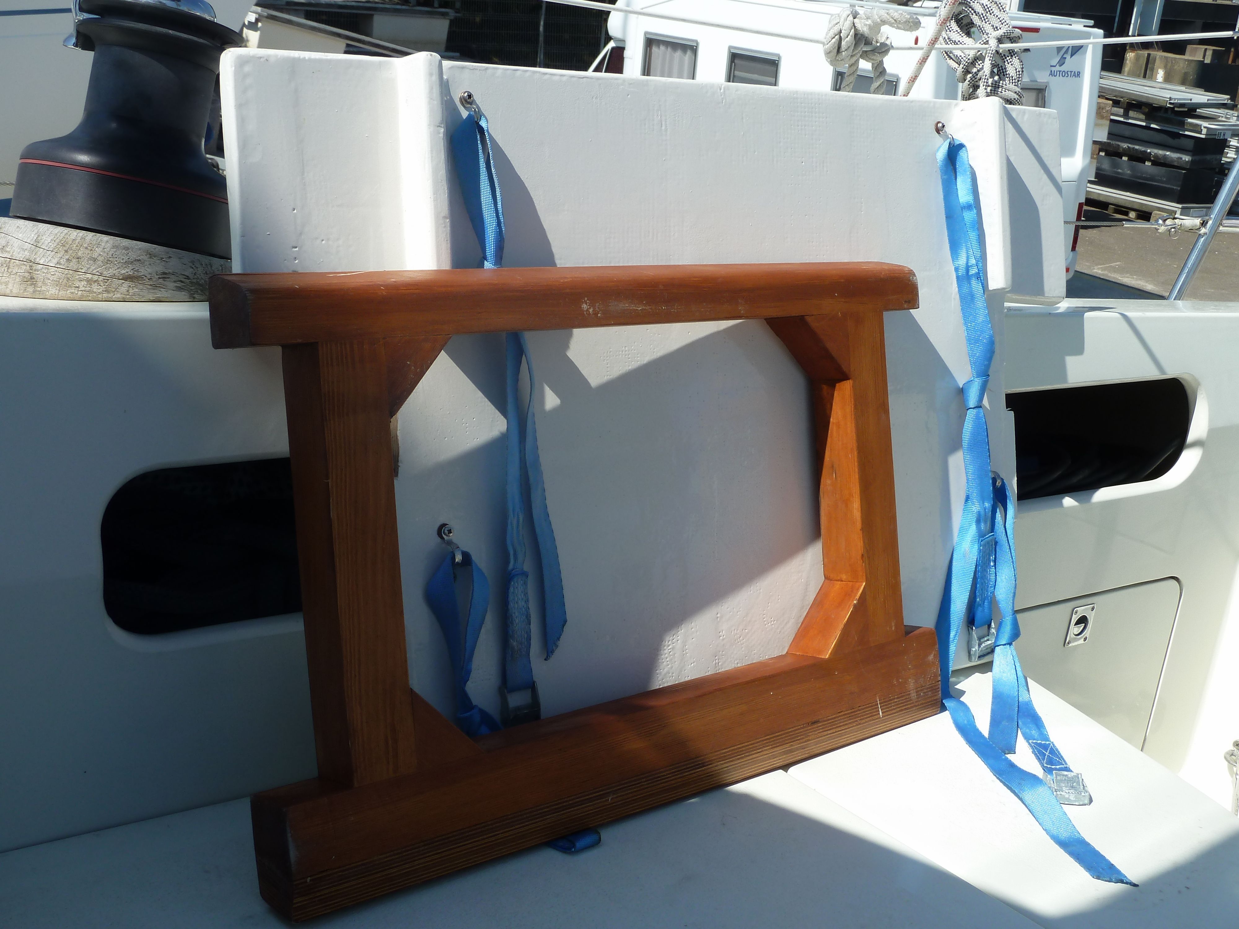
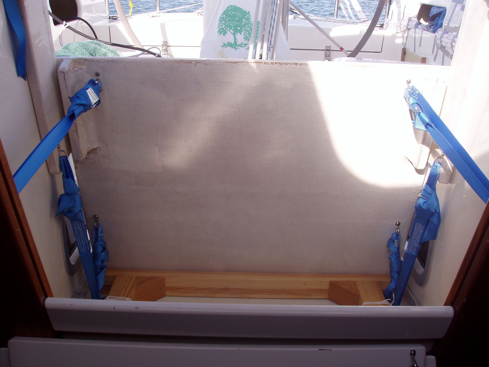
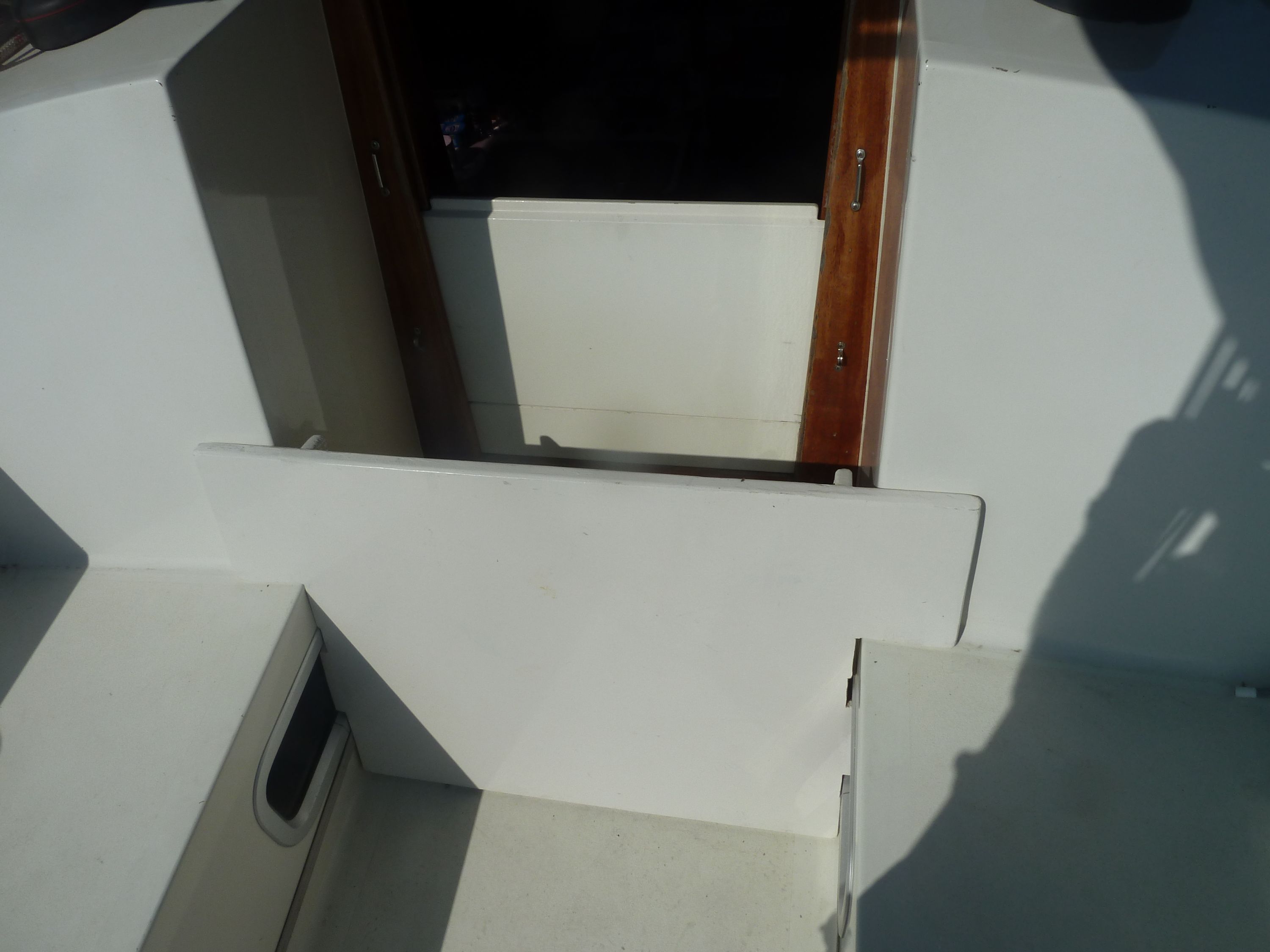
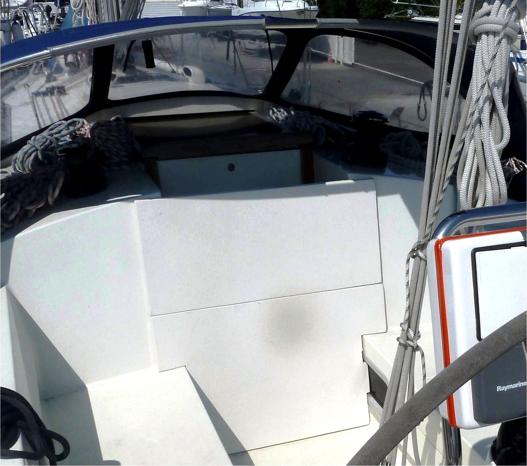
Companionway
A reinforced companionway door would be bent through by the water pressure.
One does not feel good with this solution, especially with GRP- or wood constructions.
On my yacht I divided it horizontally in two.
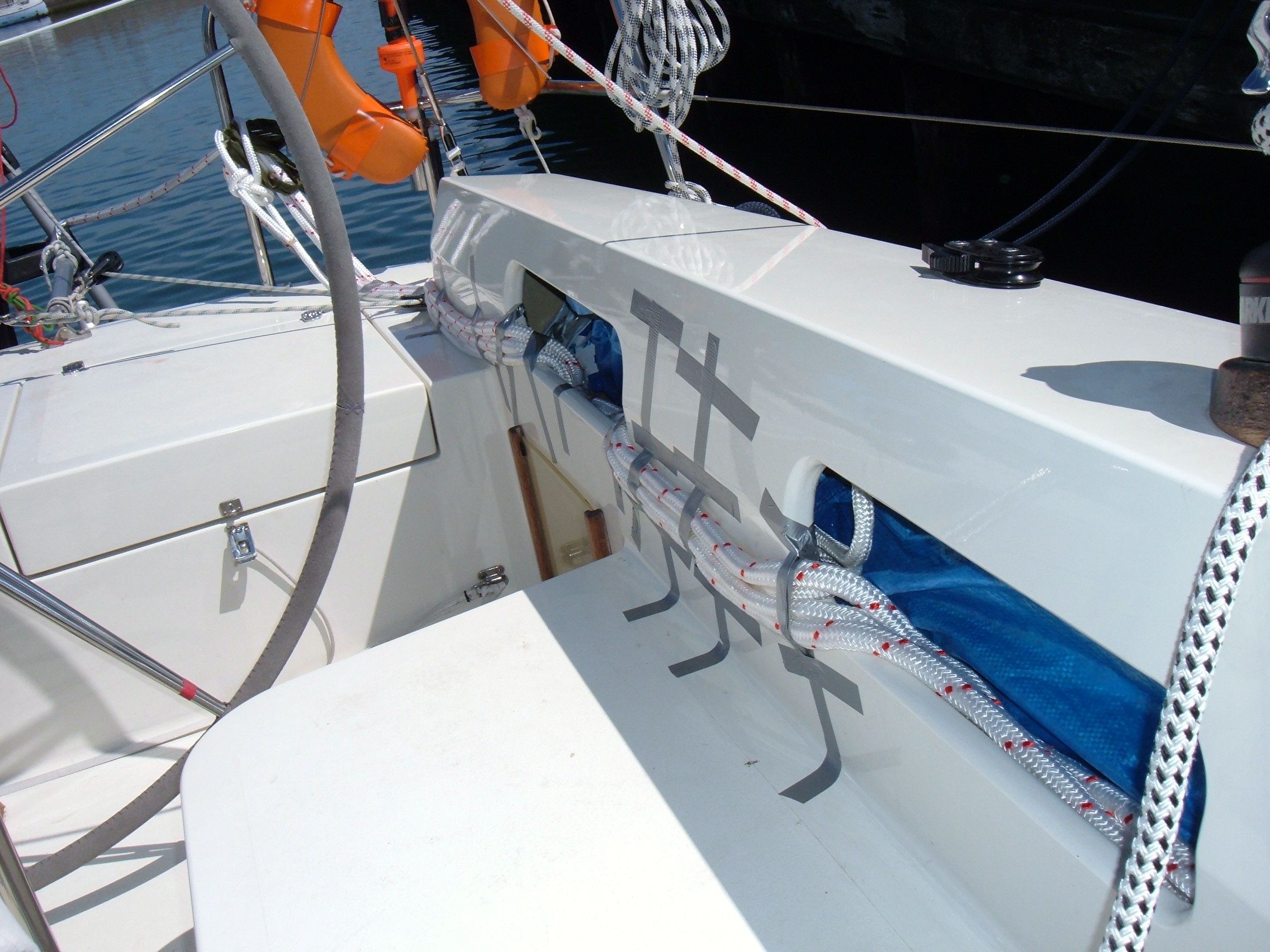
The JSD is clear for action. The weight (chain) is located in the aft sponson.
Inside the yacht
… the crew should have the possibility to hook themselves: fixed eyelets, life-lines, 3-point-belts ...
- - - - -
The dry figures given by Jordan only convey a weak picture of that what happens to a ship which got into a breaking sea.
Nevertheless a yacht which not has been upgraded is better under way under Jordan drogue than whithout.
But when the yacht has been reinforced appropriate (or she has been designed in this way from the beginning) she will have a real chance
- - - - -
Footnotes
1) 1 g corresponds ~ 9,81 m /sec2, 2 g thus ~ 19.62 m/sec2.
2) When a current is impinging on some obstacle at the speed v and is slowed down entirely
then there will result a density ρ of the seawater of 1025 kg/m3.
p = 0,5 * 1025 kg/m³ * 4,5² m²/s² = ~ 10378 ((kg * m2) : (m3*s2)
= kg : (m*s2) = (kg * m): (m²*sec2) = 10378 N/m² .
1 N matches the weight of 100 gr, thus 10378 N will match the weight of 1037,8 kg.
(according to Dr. W. Sichermann)
Jordan does not mention whether he has calculated with some security surcharge.
3) ~ 1 m2 of carbon-epoxy-plate (CFK), 3 mm thick at the moment (2010) costs about 650,- €;
~ 1 m2 carbon- Platte, 1 mm, about 325,- €;
It is possible to work plates of carbon reasonably normal: sawing, drilling, bonding; the cutted edges have to be sealed.
4) Dipl.-Ing. Dr. Ulrich Schleicher performed the calculations for it.
The following parameters have been assumed:
- The pressure does not developp abruptly; area: 1 m2; marine ply: 8 mm;
zero line of compression-tension: on the border beween two materials
- Tensile strength of the bidirectional glass fabric: 1300 N/mm2
(according to www.carbon-blog.de)
- Security surcharge: 100 % .
The carbon-composite-door approximately would reach 830 N/mm2.
This and all the following constructive proposals are from Dr. Ulrich Schleicher.
David Lynn, „Heavy Weather Sailing – Making a Series Drogue”, www.nineofcups.com.
Here you can find dimensions for the stainless steel mounting plates with other displacements.
6) The report may be downloaded from the internet inter alia from Wikipedia, keyword: “Jordan Series Drogue”.
Conversion of English measurements:
1 inch (in) = 2.54 cm / 1 foot (ft) = 30 m / 1 pound (lb) = 0.45 kg
7) Calculation with the following figures: elongation at break of steel 500 N/mm2; drag 4000 kp, reliability 50 %.
With stainless steel the elongation break is somewhat smaller, therefore ~ 20 mm.
8) Lateral force = 4200 kp x sin 20 (angle of drag) = 1436 kp; at 30o it would be 2100 kp.
The square tube prevents deformation of the lateral mounting plates (outside at the hull) namely that they don`t bend inward,
I researched to the best of my knowledge and belief. We calculated and I translated as good as possible.
The explanatory photos have been taken at our yacht "SUMMERTIME".
Dr. Lampalzer, Feb. 2018